


Inventor: Tariq Malik
Brief Summary of the Invention
A coke and water containment system has been developed which provides operators of delayed coking units improved margins of safety in draining, unheading and decoking coke drums. This invention utilizes on an exemplified embodiment, concentric cylindrical shields to provide a mechanical shield to protect personnel on the coker switch deck from coke avalanches and hot water.

Figure 1
FIG. 1 Is an elevated view of the lower portion of a coke drum having a lower end that is supported above a switch deck floor. A circumferential safety shield is supported at the lower end portion of the coke drum and is moveable between a lower position employed during the initial stages of unloading of the coke drum and an upper position after the unloading initial stages are completed. In FIG. 1 the circumferential shield is shown in it’s lower position.
Safety in draining, unheading and decoking
In one application an outer moveable containment shield is stored up against the bottom of the coke drum and is latched in place when not in use. A stationary upper inner shield is stored inside the moveable assembly. The diameter of the outside containment shield is greater than the diameter of the coke drum. The outer containment shield has hydraulic actuators and latches to allow it to be lowered so that the bottom of the shield comes to rest on a sealing medium provided on its bottom edge on the switch deck floor. In one installation a canvas fire hose was installed as the sealing medium.
A coke discharge telescoping cylinder is stored in a lower position below the switch deck floor. It is concentric with the coke drum and is designed to provide the maximum diameter available based upon the opening in the switch deck designed for coke to pass through. The other end of the chute is designed to mate with the bottom head of the coke drum when the cylinder is in the raised position. After quenching a coke drum is complete and the quench water is drained partially, fully or not at all according to the operators choosing, then the outer containment shield is deployed.
The coke drum is then unheaded inside the containment system utilizing automatic unheading technology provided by others. One installation includes a remotely controllable boltless fitting on the piping connection to the bottom head and a commercially available unheading device. If the operator desires to partially or fully drain the coke drum or to be certain that drainage is complete. The bottom head is lowered only a few inches until draining is complete. The water is contained safely by the shield and passes through the switch deck to the coke handling system where it is piped away. Then the head is swung completely away and the telescopic cylinder for the discharge of coke is raised and latched in place. Then the hydraulic decoking procedures are begun with the cutting of a pilot hole. If a coke avalanche should occur, it is contained within the containment system.
When the drum is completely decoked the outer shield can be raised and latched again safely in the storage position and the telescopic cylinder is returned to its storage position so any excess coke that got between the cylinders and the shield can be washed through the opening in the switch deck into the pit or pad below.
FIG. 2 Is an elevated view, but showing the shield broken away to reveal mechanisms of the coke drum that are within the shield when the shield is in its downward position and showing one type of bottom flange operating mechanism by which the lower end of the coke drum is closed. FIG. 2 shows the bottom flange nearly fully opened.
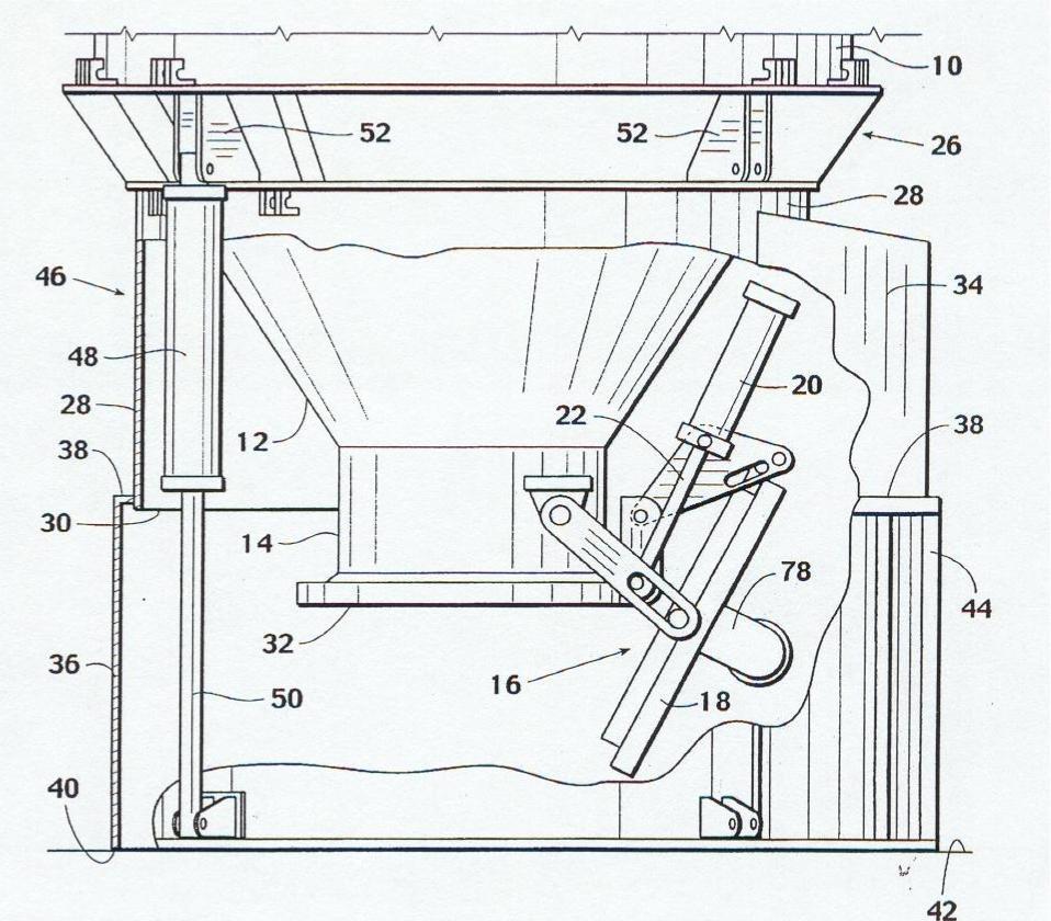
Figure 2
FIG. 3 Is an elevated view of the lower end portion of a coke drum as shown in FIG. 2 but the view is rotated 90* and the circumferential shield is shown near its retracted or upper position.
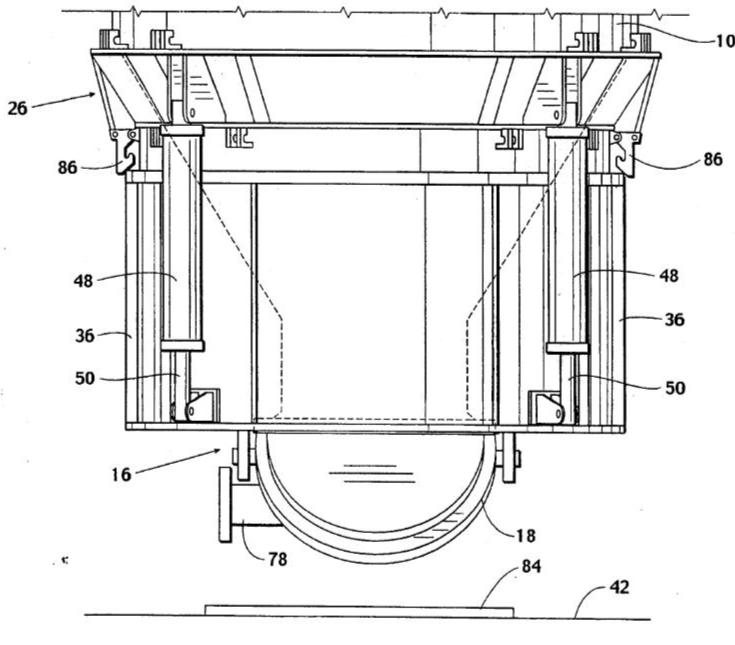
Figure 3
FIG. 4 Is a view of bottom portion of a coke drum with the circumferential safety shield in its upper or retracted position and showing the bottom flange in a closed position and showing piping extending from the bottom flange.
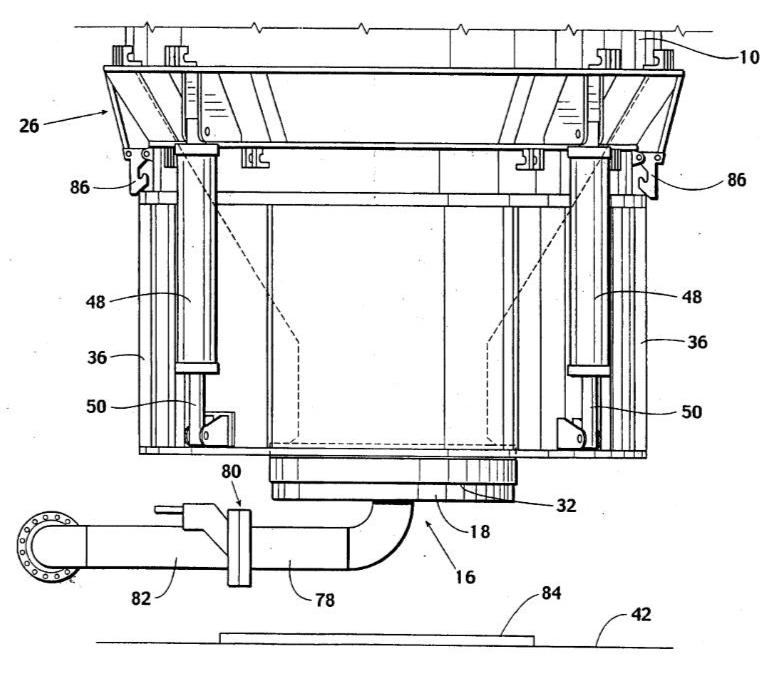
Figure 4
For more information contact Tariq Malik.
Leave a Reply
You must be logged in to post a comment.