Hey People, ever get plugged taps on flow meters? Absolutely!
Unit fresh feed, heater pass flow, recirculation system….etc. Any system with heavy oil and solids can have those tiny little impulse lines plug with coke or other solids. Over the years, we have seen all sorts of ways to remove those solids and minimize plugging. Just off the cuff, I can remember three:
- Continuous purge system (not good due to excessive gas oil use)
- Portable pumper hand-cart (not good because the operator has to be nearby to clear the path before tripping the heater)
- Special block valves with rod through capability (not good due to safety risk to the operator)
Well, here is another idea, a mechanical auto-rodder that frequently ‘scrapes’ the tapping point clear on the orifice plate flow meter automatically which helps keep the impulse line clear. Tripping the coker heater on low flow is a problem in all sorts of ways. We can consider the safety risk during relighting the furnace. Then, we consider the incremental fouling that occurs when the heater trips and dumps the emergency steam. If your heater suffers from spurious trips on low flow, consider this solution. Let us know your thoughts…. – the Coking.com Team
Eliminating Plugged Impulse lines & Tapping Points
Improving Field Instrument Reliability & Unit Efficiency
Example – Sulfur process
Background
Sulfur (periodic table symbol S) – atomic number 16 – is one of the building blocks of life. In its elemental form, it can be found as a solid yellow crystalline substance. Today, Sulfur is mostly produced as a byproduct of removing Sulfur containing contaminants of Natural Gas and Oil.
The most widely used commercial product containing Sulfur is Sulfuric Acid (H2SO4). Sulfuric acid is used in fertilizer, insecticide, gasoline, match and fungicide manufacturing.
Sulfur is a solid with a melting point of 115°C (239°F), a boiling point of 446°C (835°F) and a liquid density of 1.8 at melting point.
Sulfur burns easily and creates Sulfur dioxide (SO2) gas which has a choking, suffocating odor. Sulfur also combines naturally in living organisms with Hydrogen, creating Hydrogen Sulfide (H2S) a toxic pungent (rotting egg) gaseous element.
This makes handling Sulfur (extracting, processing and storing) in the petroleum refining industry a challenge.
Furthermore, petroleum refineries using Sulfuric acid in their SAAU (Sulfuric acid alkylation unit) also need to deal with the inherent properties of Sulfur.
The problem primarily relates to the melting point of 115°C (239°F).
The most efficient, cost effective method to transport Sulfur is in its liquid format temperatures above the melting point. It is also most cost effective to generate sufficient energy to maintain this temperature than having to go far above it.
Management Device
Measuring Pressures, Flow Rates and Level is best done around the melting point and where possible the field instrument of choice is the absolute or gauge pressure transmitter and differential pressure transmitter. For the purpose of this exercise, let’s group them together as Pressure Transmitters.
Pressure transmitters are accurate, reliable, robust and economical. They are by far the most popular process variable measurement device on our planet. The same Pressure transmitter can be used to measure pressure as well as level in a barometric tank. The same Differential Pressure transmitter can be used to measure level in a pressure vessel, flow across an Orifice Plate or Venturi and Density.
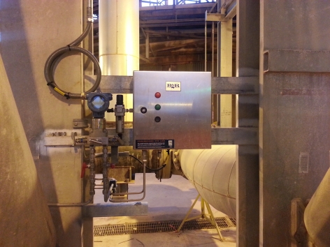
Fig. 1.0 – Differential Pressure Transmitter and local Autorodder Control Box
There are many quality manufacturers and most qualified instrument technicians are taught how to install, operate and service these devices during their relevant apprenticeship or study cycle.
Pressure transmitters are a CONTACT device. They need to be in contact with the process to measure the variable accurately. There are a multitude of installation configurations but all follow a simple philosophy.
If the Process is clean the installation is simple. If the process is dirty – such as Sulfur – the installation is a little more complex.
Installation Recommendations
Processes such as Sulfur that crystallize on surfaces, inside cavities, on elbows and bends, below 115°C (239°F) cannot come into direct contact with a Pressure Transmitter.
The recommended solution is to introduce an inert, clean purge as a barrier between the Field instrument and the process. Details such as keeping impulse lines as short as possible and correct installation practices can be found at: http://goo.gl/8qiCd0
In a perfect environment accurate process variable measurement can now be assured.
Unfortunately we do not live in a perfect world.
Current Problems – Mechanical
Massive problems occur each and every day with plugged impulse lines and tapping points. It all starts with the physical installation. If there are location issues, such as platforms, walkways, bends and walls, it may not be possible to keep impulse lines between pressure transmitter and tapping point as short as possible.
Sulfur has a density of 1.8 at its melting point. Most inert purges will have a lesser density. The molten sulfur will displace the purge in a horizontally installed tapping point. This means Sulfur will work its way into the bore of your isolation valve and possibly all the way into the impulse line.
Purge must be heated to the same or higher temperature than the molten Sulfur, if not, Sulfur crystals will occur at the purge/Sulfur interface.
Impulse lines, tapping points and tapping point isolation valves need to be heat traced or steam jacketed to prevent cooling of the tubing, piping or valve. Any drop below 115°C (239°F) will result in crystals forming inside the bore.
Generating and pre-heating purge is very expensive, using this product to blast open a plugged tapping point is therefore not cost effective.
Current Problems – Process Measurement
As expressed above, in a perfect world, accurate process variable measurement allows for accurate control which allows for optimum efficiency from your Sulfur process plant.
These are real life issues: Even with steam jacketing, reliable purge, heat tracing and inclined tapping point installations Sulfur crystals will form over time at the tapping point/process pipe or tank interface. Over time as this primary pressure measurement point starts to gradually plug, the bore of the tapping point will reduce in diameter, purge flow gets restricted leading to spurious process variable feedback to the control room. Operators lose confidence in the field device.
Furthermore, as the bore of the tapping point reduces in diameter, it will get smaller than the bore of your impulse line. Induced errors come into play with purge backpressure adding to the process pressure and confusing operators, even worse is the fact that some Sulfur crystals will migrate into the bore of the Isolation valve and further on down into the bore of the impulse line. Over time the impulse line becomes plugged rendering the accurate, robust field instrument ineffective.
Current Symptomatic Solutions and Failures
So much of current strategies to overcome plugged impulse lines and tapping points focus on the symptoms and not the core problem.
- Let’s ditch the Pressure Transmitter and go non-contact……. If your Refinery has a bunch of Pressure Transmitters and you now want to go through a change out, hope you have deep pockets. What will you use? Nucleonics, Radar, Ultrasonic, Magnetic or Load Cells etc. Sure these non-contact instruments are highly sophisticated, but also quite expensive, can be fragile and have limitations. Most will require proprietary tools, training and service arrangements to operate satisfactorily.
But why?
The Pressure or Differential Pressure Transmitter is NOT the problem
- Let’s increase diameter of tapping point so that it takes a lot longer to plug. A Pressure Transmitter only needs a small opening to measure the process. This tapping point must have a larger bore than the Impulse line and probably the most convenient size would be a 3/8” impulse line leading into a 1” tapping point. If you head to 1 ½”, 2” or even larger diameter tapping points, you need larger diameter and heavier isolation valves and stronger nozzles, all of this a lot more expensive.
But why?
The diameter of the tapping point is not the problem
- Let’s blast purge through the impulse line and tapping point. Purge is expensive, it is inert, it will need to be heated and experience has shown crystallization of Sulfur in the bore of the tapping point will still take place. In most cases whatever amount of purge you introduce via the tapping point has to be removed from the process later on. Purge can be parasitic.
But Why?
Reducing the rate of flow of purge should be the goal
- Let’s send out highly trained technicians to manually drill or rod out the tap. Wow – would you like to do that job? How risky is it to send a technician out in the middle of a freezing night up several flights of stairs to a platform to rod out a plugged tap? No explanation necessary, suffice to say lost time injuries from rodding out tapping points is a blight on our industry.
But Why?
Risking life and limb to unblock a recurrent blockage is expensive and silly
- Let’s just ignore the inaccurate measurement, we only have a few weeks to a unit outage, we’ll be O.K. until then! Yeah right. How many times have there been shutdowns, unit outages, carry over and spillage of molten Sulfur because process variable measurement was lost, ignored or inaccurate?
The common thread in all of the above is the treatment of the symptoms of plugging impulse lines and tapping points but not actually solving the problem.
What is the Solution and Why?
The solution is simple: Prevent any partial build-up or plugging of the tapping point using an Autorodder. Maintain a bore (Inside Diameter) greater than the bore of your impulse line. Ensure safety is priority number one with respect to impulse line location and bleed/vent indication location. Install on an incline wherever possible.
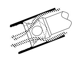
It is critical that the Autorodder is installed as a preventative maintenance apparatus. It will stroke frequently as necessary to keep the tapping point clean. It must stroke automatically and ensure that there are no induced errors or spikes during the stroking cycle.
Modus Operandi
A patented Tapping Point Clearing Apparatus, includes a Scraper with a profile, annulus and holes that can be cycled through an Instrument tapping point at a predetermined frequency. At no point during the stroking cycle does the scraper ever block or constrict the bore of the tapping point. It begins its journey from behind the Tapping Point Isolation Valve, through the bore of the valve, through the inside of the nozzle and into the process stream where any solids are dissolved and washed off the scraper, some 1- 2 seconds later it returns to its starting point behind the Isolation valve.
Why is the Autorodder a Solution?
By stroking a custom built scraper through the tapping point at a pre-determined frequency (anywhere from once per five minutes to once per day or week) The Autorodder provides the following benefits:
- The Pressure Transmitter and Differential Pressure Transmitter can be used in dirty, crystallizing applications reliably and confidently. No need for expensive NON-CONTACT field instruments.
- Purge flow can be reduced to an absolute minimum so that it can do its job and that is act as a barrier.
- Technicians are never exposed to the risky practice of manually rodding out plugged tapping points.
- Accurate and reliable process variable measurement = accurate process control = maximum unit efficiency.
- By maintaining a clear tapping point, eliminating any possible purge back flow, plugged impulse lines are no longer a problem.
- Spurious outages or unit shutdowns from plugged tapping points become obsolete.
- The Apparatus can be locally operated and controlled or connected to your DCS.
- The Apparatus requires no special tools, is field serviceable and interchangeable.
Examples
In 2005, Autorodders were installed on a Sulfur loading facility to assist in safe and accurate tanker loading. Spillage must be zero as the location is in an environmentally sensitive area. To date there has been zero spillage, and zero servicing requirement of the Autorodders. The units have cycled some 62,400 times each.
In 2009, Autorodders were installed on a 2 out of 3 pressure safety shutdown system on a coal fired draft boiler operating at 1400°C (2552°F). Process Operating pressure to be maintained was between the range -3 KPa to +3 KPa ( -0.435psi to + 0.435psi). Keeping tapping points clear of soot, ash and crystals, there has be no spurious outage and service free operation for 4 years.
Conclusion
Finally a simple field serviceable apparatus that solves the age old problem of plugged impulse lines and tapping points, not treat the symptoms. Clearguard Pty. Ltd. is the proud sponsor of the Wednesday Evening Networking Reception at RefComm® Galveston 2017. Our team will be available for questions and discussion at booth #37 during the RefComm® event. For more immediate information, please visit our website – http://clearguard.com
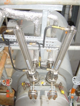
Fig 2.0 – Ethylene Cracked Gas Flow Venturi
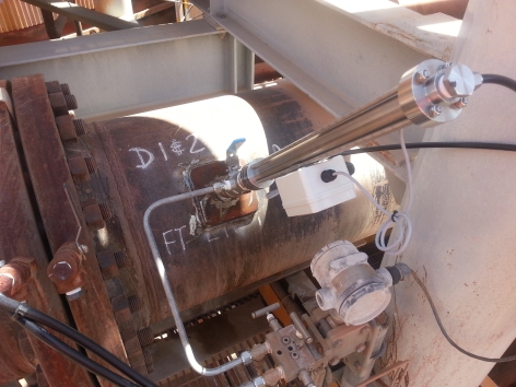
Fig 3.0 – Sodium hydroxide liquid slurry Flow Orifice Plate
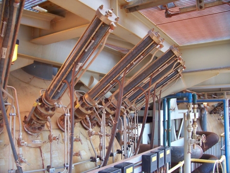
Fig 4.0 – Pressure measurement 2 out of 3 Safety Shutdown and Level Measurement High Pressure Vessel Fieldbus Communication direct to DCS
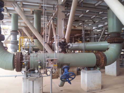
Fig 5.0 – HP Pump Manifold Pressure Measurement
c/w Double Block and Bleed Isolation Valve


Leave a Reply
You must be logged in to post a comment.